
6.6 Technical Feasibility Assessment
With a “Yes” decision, it is time to move into the Technical Feasibility Assessment phase. During this phase the designer will fine-tune the selection of equipment that will be used as part of the cogeneration plant.
1. Identifying Sizing Options and Operating Modes
- Since different vendors offer different sizes of equipment, it is time to determine the sizes for each piece of equipment. The size of the generator, engine radiator or cooling tower, heat recovery components, and use of the waste heat must be determined. If the CHP plant will incorporate a cooling option, the size of the absorption chiller must all be determined since this will impact the heat recovery component selection and cooling tower size.
- In parallel to determining the size of all key equipment, the designer must determine the various operating modes that the system will encounter. It is extremely important to understand the electric load profile on a 24 hour / 7 days a week basis including any start-up variations. It is also important to determine how the customer will use the waste heat from the generator plant. This combination of the electric load profile and how the waste heat will be used is key to sizing the generator plant, determining the number of generators to be used and whether the use of exhaust gas heat recovery is justified.
- Engineering analysis must include an evaluation of the optimum configuration for both power production and heat recovery operations. For instance, engines are better suited for start-stop operations and generally provide a lower quality heat. Turbines and microturbines perform better in base loaded applications and excess oxygen in the exhaust allows easy adaptation of duct burners and other process heating applications. Two or three units may provide much greater flexibility and reliability than a single unit and may make available for consideration much lower-cost packaged CHP systems (both microturbine and small engine CHP systems are commercially available).
- The above information will feed into the next step.
2. Develop CHP System Conceptual Design
- With final selection of equipment and operating modes known, the designer can begin developing the conceptual system design.
- The designer should start by obtaining a diagram for the electrical circuit currently in use by the customer. This allows the designer to determine what electrical components are required to interface the generator with the customer circuit. It will also be used to identify the required voltage for the generator or if any additional transformers and switchgear is required. This will be particularly important for those systems that parallel with the utility.
- After developing the generation portion of the Conceptual System, the designer must determine the most practical use of the waste heat. This decision should have been made during the Technical Feasibility Assessment phase.
- The ability to control and automatic CHP operation has proven to be a very crucial element in most industrial applications. Appropriate designs can improve system economies.
- Figure 6-2 shows a simplified version of a typical cogeneration plant that uses the generator waste heat to drive a single stage absorption chiller. Even in this simplified design, it is important to know a variety of flows and temperatures.
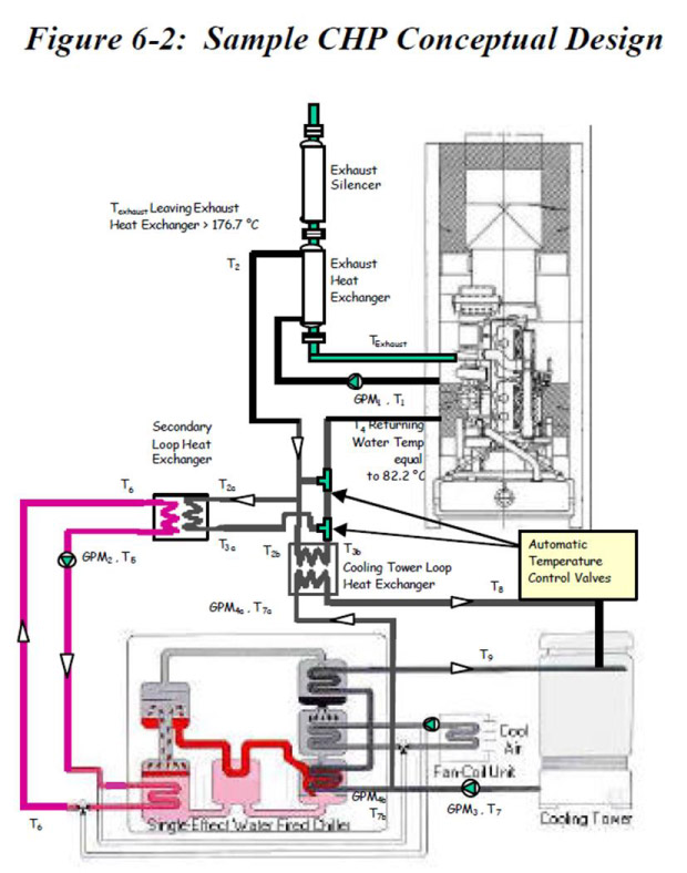
Flows and Temperatures that must be determined for all operating modes
T1 – Leaving Engine Coolant Temperature
T2 – Leaving Exhaust Heat Exchanger Coolant Temperature
T2a – Entering Secondary Loop Heat Exchanger Coolant Temperature (Primary Side)
T2b – Entering Cooling Tower Loop Heat Exchanger Coolant Temperature (Primary Side)
T3a – Leaving Secondary Loop Heat Exchanger Coolant Temperature (Primary Side)
T3b – Leaving Cooling Tower Loop Heat Exchanger Coolant Temperature (Primary Side)
T4 – Entering Engine Coolant Temperature (Should be 82.2 ?C)
T5 – Leaving Secondary Loop Heat Exchanger Water Temperat ure (Secondary Side) and Entering Absorber
Generator
Water Temperature
T6 – Leaving Absorber Generator Water Temperature and Entering Secondary Loop Heat Exchanger Water
Temperature
(Secondary Side)
T7a – Entering Cooling Tower Loop Heat Exchanger Water Temperature (Secondary Side)
T7b – Entering Absorber Condenser Water Temperature
T8 – Leaving Cooling Tower Loop Heat Exchanger Water Temperature (Secondary Side)
T9 – Leaving Absorber Condenser Water Temperature
Texhaust – Exhaust Temperature Leaving Engine and Entering Exhaust Heat Exchanger
Texhaust Leaving – Exhaust Temperature Leaving Exhaust Heat Exchanger (Must be Greater than 176.7 ?C)
GPM1 – Engine Coolant Circuit Flow Rate
GPM2 – Absorber Generator (Secondary Loop) Flow Rate
GPM3 – Cooling Tower Flo w Rate
GPM4a – Cooling Tower Loop Heat Exchanger Flow Rate
GPM4b – Absorber Condenser Flow Rate
Note: Flow Rates GPM4a and GPM4b equals Flow Rate GPM3