
4.4 Fuel Cells
The first electro chemical fuel cell was invented in 1839, however, it wasn’t until the 1960’s space program that practical applications were realized. Fuel cells have been the energy source aboard each manned space flight in the U.S. Since early 1990’s fuel cells have been used as stationary power systems. Fuel cells are clean, quiet and reliable power generators which makes them suitable for several commercial and industrial applications. Other than auxiliary pumps and fans fuel cells have virtually no moving parts, which makes them extremely quite compared to conventional prime movers. Fuel cells fueled with hydrogen produce no pollutants. For stationary applications hydrogen fuel is uncommon so the typical fuel is natural gas. The hydrogen rich fuel in natural gas is utilized in the electrochemical process leaving a bi-product of CO2.
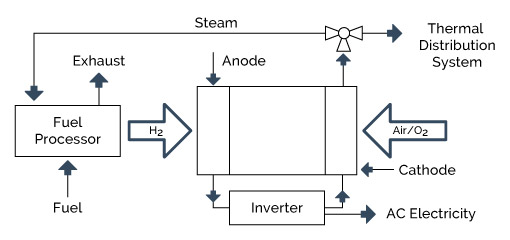
A schematic of a fuel-cell-based CHP system is shown in Figure 4-8.
The fuel cell industry continues to mature; however, there are a limited number of commercially available options. As with most new technologies, fuel cell system have a relatively high capital cost. This has been a key factor in inhibiting wide scale commercialization. Despite the high costs, the inherent reliability and environmental attributes have led to early adoption by municipalities, food retail, educational facilities, hospitals and data centers. Commercial systems have demonstrated excellent reliability and have been used in critical power applications. The many advantages of fuel cells over other prime movers suggest that they could well become the prime mover of choice for many applications and products in the future.
Fuel cells produce power electrochemically from hydrogen delivered to the negative pole (anode) of the cell and oxygen delivered to the positive pole (cathode). The hydrogen can come from a variety of sources, but the most economic method is by reforming of natural gas or liquid fuels. There are several different liquid and solid media that support these electrochemical reactions – phosphoric acid (PAFC), molten carbonate (MCFC), solid oxide (SOFC), and proton exchange membrane (PEM) are the most common systems. Each of these media comprises a distinct fuel cell technology with its own performance characteristics and unique advantages and disadvantages. Direct electrochemical reactions are generally more efficient than using fuel to drive a heat engine to produce electricity. Fuel cell efficiencies range from 35-42 percent for the PAFC to upwards of 60 percent for MCFC and SOFC. Fuel cells are inherently quiet and have extremely low emissions levels. Like a battery, fuel cells produce direct current (DC) that must be run through an inverter to get 50 or 60 Hz AC. These power electronics components can be integrated with other power quality components as part of a power quality control strategy for sensitive customers. Because of current high costs, fuel cells are best suited to environmentally sensitive areas and customers with power quality concerns.
4.4.1 Technology Description
This section describes five types of fuel cell technologies for a variety of distributed generation (DG) applications. These are: 1) phosphoric acid (PAFC), 2) proton exchange membrane (PEMFC), 3) molten carbonate (MCFC), 4) solid oxide (SOFC), and 5) alkaline (AFC). Each type is distinguished by the electrolyte used and by operating temperatures. These fuel cells operate from near-ambient temperature to above 1,000° C. As a result, they can have very different performance characteristics, advantages and limitations, and therefore will be suited to DG applications in a wide variety of approaches.
The different fuel cell types share certain important characteristics. First, fuel cells are not Carnot cycle (thermal energy-based) engines. Instead, they use an electrochemical or battery-like process to convert the chemical energy of hydrogen into water and electricity. As simple cycle devices, they can achieve extremely high electrical efficiencies. The second shared feature is that they use hydrogen as their fuel, which is typically derived from a hydrocarbon fuel such as natural gas. Third, each fuel cell system is composed of three primary subsystems: 1) the fuel cell stack that generates direct current electricity; 2) the fuel processor that converts the natural gas into a hydrogen-rich feed stream; and 3) the power conditioner that processes the electric energy into alternating current or regulated direct current. Finally, all types of fuel cells emit minimum emissions. This is because the only combustion process is the burning of a low energy hydrogen exhaust stream that is used to provide heat to the fuel processor.
Fuel cells produce direct current electricity through an electrochemical process, much like a standard battery. Unlike a standard battery, the fuel cell is chemically replenished on a continuous basis. The reactants, most typically hydrogen and oxygen gas, are fed into the fuel cell reactor, and power is generated as long as these reactants are supplied. The hydrogen (H 2 ) is typically generated from a hydrocarbon fuel such as natural gas or LPG, and the oxygen (O 2 ) is from ambient air.
Basic Processes and Components
Fuel cell systems designed for DG applications are primarily natural gas systems. Each fuel cell system is composed of three primary subsystems: 1) the fuel cell stack that generates direct current electricity; 2) the fuel processor that converts the natural gas into a hydrogen rich feed stream; and 3) the power conditioner that processes the electric energy into alternating current or regulated direct current.
In a fuel cell it is the change in the Gibbs free energy of formation that results in energy release. This change is the difference between the Gibbs free energy of the product and the Gibbs free energy of the reactants. Water (H 2 O) is the chemical product of this process. The overall reaction in a fuel cell is characterized as follows:
2H 2 (gas) + O 2 (gas) —> 2H 2 O (vapor) + Energy
The hydrogen and oxygen gases are not directly mixed and combustion does not occur. Instead, the hydrogen is oxidized one molecule at a time, in the presence of a catalyst. Because the reaction is controlled at the molecular level, there is no opportunity for the formation of NO x and other pollutants as there is inside piston and turbine engines.
Figure 4-9 illustrates the electrochemical process in a typical single cell, acid-type fuel cell. The hydrogen and oxygen are fed to the anode and cathode, respectively. The anode and cathode are electrically conductive, porous electrodes separated by an ionic conductive (non-electrically conductive) media, known as the membrane, ionic matrix or electrolyte layer. At the anode the hydrogen gas is electrochemically dissociated into hydrogen ions (H + ) and free electrons (e – ). The half-cell reaction is the following
2H 2 (gas) —> 4H + + 4e – E o = 0.0 volts
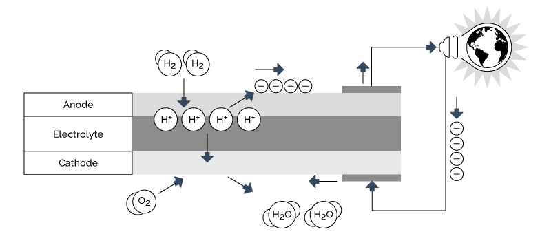
Figure 4-9: Fuel Cell Electrochemical Process
The electrons flow out of the anode through an external electrical circuit. The hydrogen ions flow into the electrolyte layer and eventually to the cathode, driven by both concentration and potential forces. At the cathode the oxygen gas is electrochemically combined with the hydrogen ions and free electrons to generate water. The half-cell reaction is the following:
O 2 (gas) + 4H + + 4e – —> 2H 2 O (vapor) E o = 1.23 volts (LHV) (1), or
O 2 (gas) + 4H + + 4e – —> 2H 2 O (liquid) E o = 1.48 volts (HHV) 34
As power is generated, electrons flow through the external circuit, ions flow through the electrolyte layer and chemicals flow into and out of the electrodes. Each process has natural resistances that must be overcome, which reduces the operational cell voltage below the theoretical potential. Therefore, some of the chemical potential energy is converted into heat. The electrical power generated by the fuel cell is the product of the current measured in amps and the operational voltage. Based on the application and economics, a typical operating fuel cell will have an operating voltage of between 0.55 volts and 0.80 volts. The ratio of the operating voltage and 1.48volts represents a simplified estimate of the stack electrical efficiency on a HHV basis. As stated, resistance heat is also generated along with the power. Since the electric power is the product of the operating voltage and the current, the quantity of heat that must be removed from the fuel cell is the product of the current and the difference between the Gibbs free energy potential and the operating voltage. In most cases the water produced by the fuel cell reactions exits the fuel cell as vapor, and therefore, the 1.23-volt LHV free energy potential should be used to estimate sensible heat generated by the fuel cell electrochemical process.
Practical fuel cell systems require voltages higher than 0.55 to 0.80. This is achieved by combining several cells in electrical series into a fuel cell stack. Typically, several hundred cells are use in a single cell stack. The current is managed by increasing the active area of individual cells. Typically, cell area can range from 100 cm 2 to over one m 2 depending on the type of fuel cell and application power requirements.
Fuel Processors
In distributed generation applications, the most viable fuel cell technologies use natural gas as the stock fuel. To operate on natural gas or other fuels, fuel cells require a device that converts the stock fuel into the hydrogen-rich gas stream. This device is known as a fuel processor or reformer. While adding fuel flexibility to the system, the reformer adds significant cost, complexity, and the potential for undesired emissions. There are three primary types of reformers: steam reformers, autothermal reformers and partial oxidation reformers. The fundamental differences are the source of oxygen used to combine with the carbon within the fuel to release the H2 gases and the thermal balance of the chemical process. Steam reformers use steam; while partial oxidation units use oxygen gas and autothermal reformers use both steam and oxygen. Partial oxidation units combust a portion of the fuel (i.e. partially oxidize it), the thermal balance is exothermic and releases heat.
Steam reforming is extremely endothermic and requires a substantial amount of heat input. Autothermal reformers are typically operated at or near the thermal neutral point, and therefore, do not generate or consume thermal energy. When integrated into a fuel cell system that allows the use of anode-off gas, a typical natural gas reformer can achieve efficiencies in the 75 to 90% LHV range with 83 to 85% being an expected characteristic. These efficiencies are defined as the LHV of hydrogen generated divided by the LHV of the natural gas consumed by the reformer.
Some fuel cells can be constructed and operated as internally steam reforming fuel cells. Since the reformer is an endothermic catalytic converter and the fuel cell is an exothermic catalytic oxidizer, the two are combined into one with mutual benefits from the thermal processes. More complex than a pure hydrogen fuel cell, these types of fuel cells are more difficult to design and operate. While combining two catalytic processes is difficult to arrange and control, these internally reforming fuel cells are expected to account for a significant market share as fuel cell-based DG becomes more common.
Power Conditioning Subsystem
The fuel cell generates direct current electricity, which must be conditioned before being used within a DG application. Depending on the cell area and number of cells, this direct current electricity is approximately 200 to 400 volts per stack. If the system is large, enough, stacks can be operated in series to double or triple individual stack voltages. Since the voltage of each individual cell decreases with increasing load or power, the output is considered an unregulated voltage source. In the power conditioning subsystem, the output voltage can be boosted to provide a regulated higher voltage input source to an electronic inverter. The inverter then uses a pulse width modulation technique at high frequencies to generate simulated alternating current output. The frequency of the output is controlled by the inverter and can be adjusted to enhance power factor characteristics. Because the alternating current is generated within the inverter the output power is considered to be a very clean, reliable source. This characteristic can be important to sensitive electronic equipment in premium power applications. The efficiency of the power conditioning process is typically 92 to 96%, and is dependent on system capacity and input voltage current characteristic.
Types of Fuel Cells
There are five basic types of fuel cell under consideration for DG applications. The fuel cell’s electrolyte or ion conduction material defines the basic type. Two of these fuel cell types, polymer electrolyte membrane (PEM) and phosphoric acid fuel cell (PAFC) have acidic electrolytes and rely on the transport of H + ions. Two others, alkaline fuel cell (AFC) and carbonate fuel cell (MCFC) have basic electrolytes that rely on the transport of OH – and CO 3 = ions, respectively. The fifth type, solid oxide fuel cell (SOFC), is based on a solid-state ceramic electrolyte in which oxygen ions (O = ) are the conductive transport ion. Each fuel cell type has been designed to operate at optimum temperatures, which are a balance between the ionic conductivity and component stability. These temperatures differ significantly among the five basic types, ranging from near-ambient to as high as 1800° F. The proton conducting fuel cell type generates water at the cathode and the anion conducting fuel cell type generates water at the anode. Table 4-5 presents fundamental characteristics for each fuel cell type.
Table 4-5: Characteristics of Major Fuel Cell Types
| PEMFC | AFC | PAFC | MCFC | SOFC | |
|---|---|---|---|---|---|
| Type of Electrolyte | H+ ions (with anions bound in polymer membrane) | OH- ions (typically aqueous KOH solution) | H+ ions (H3 PO4 solutions | CO3= ions (typically, molten LiKaCO3 eutectics) | 0= ions (Stabilized ceramic matrix with free oxide ions) |
| Typical construction | Plastic, metal or carbon | Plastic, metal | Carbon, porous ceramics | High temp metals, porous ceramic | Ceramic, high temp metals |
| Internal reforming | No | No | No | Yes, Good Temp Match | Yes, Good Temp Match |
| Oxidant | Air to 02 | Purified Air to 02 | Air to Enriched Air | Air | Air |
| Operational Temperature | 150° - 180°F (65° - 85°C) | 190° - 500°F (90° - 260°C) | 370° - 410°F (190° - 210°C) | 1200° - 1300°F (650° - 700°C) | 1350° - 1850°F (750° - 1000°C) |
| DG System Level Efficiency, % HHV | 25 to 35% | 32 to 40% | 35 to 45% | 40 to 50% | 45 to 55% |
| Primary Contaminate Sensitivities | CO, Sulfur and NH3 | CO, CO2 and Sulfur | CO < 1% Sulfur | Sulfur | Sulfur |
2012 Fuel Cell Technologies Market Report” U.S. Department of Energy, October 2013. http://energy.gov/sites/prod/files/2014/03/f11/2012_market_report.pdf
PEMFC (Proton Exchange Membrane Fuel Cell or Polymer Electrolyte Membrane)
This type of fuel cell was initially developed in the 1960s for the first NASA manned spacecraft. The PEMFC uses a solid polymer electrolyte and operates at low temperatures, about that of boiling water. Over the past ten years, the PEMFC has received significant media coverage due to the large investment the auto industry has made in the technology. Due to their modularity and apparent ease of manufacturing, much has been made of the reformer/PEMFC system for residential DG applications.
AFC (Alkaline Fuel Cell)
F.T. Bacon in Cambridge, England first demonstrated AFC as a viable power unit during the 1940s and 1950s. It was later developed for NASA, and was used on the Apollo moon mission spacecraft and on the space shuttles. The primary advantages of AFC technology are improved performance, use of non-precious metal electrodes, and the fact that no unusual materials are needed. The primary disadvantage is the tendency to absorb carbon dioxide, converting the alkaline electrolyte to an aqueous carbonate electrolyte that is less conductive. The attractiveness of AFC has declined substantially with the interest and improvements in PEMFC technology.
PAFC (Phosphoric Acid Fuel Cell)
PAFC is generally considered to be the most established fuel cell technology. The first PAFC DG system was designed and demonstrated in the early 1970s. PAFCs have been commercially available since the early 1990s and are considered to be viable in niche markets. PAFC-based systems have been installed in the U.S., Japan, and Europe, and are commercially available in the 200 to 400 kW sized packages. Larger power requirements typically gang multiple units together. When operated at elevated pressures, PAFCs are capable of fuel-to-electricity efficiencies of better than 40%. The technology on which this system is based was developed as the result of a government/industry research, development and demonstration (RD&D) effort starting in the 1970s and continuing through the early 1990s. During the 1990s, over 200 commercial units were manufactured, delivered and operated. The current products reported to have a stack lifetime of over 80,000 hours, units with over ten years of operation, and commercially based reliabilities in the 90 to 95% range. The major market barrier has been the initial installed cost.
MCFC (Molten Carbonate Fuel Cell)
The MCFC has a developmental history that dates back to the early part of the twentieth century. Due to its operating temperature range of 600 to 750° C, the MCFC holds promise in both CHP and DG applications. This type of fuel cell can be built with internal reforming, run at high efficiencies (50% HHV), and is relatively tolerant of fuel impurities. Government/industry RD&D programs during the 1980s and 1990s resulted in several individual pre prototype system demonstrations. The primary technical issue with MCFC technologies is the degradation of cell components due to the corrosive nature of the electrolyte operating temperature combination.
SOFC (Solid Oxide Fuel Cell)
SOFC systems have been commercial available and deployed since 2010. SOFC has several advantages that justify its further development. High efficiency, stability and reliability, and high internal temperatures, distinguish the SOFC from other fuel cell technologies. The SOFC has projected service electrical efficiencies of 60% and higher. Efficiencies for smaller SOFC DG units are estimated to be in the 50% range. Stability and reliability of the SOFC are high due to an all-solid-state ceramic construction.. The high internal temperatures of the SOFC are both an asset and a liability. As an asset, high temperatures make internal reforming possible. As a liability, these high temperatures add to materials and mechanical design difficulties, which reduces lifetime and increases cost. While SOFC research has been ongoing for 30 years, costs of these stacks are still comparatively high.
4.4.2 Performance
Table 4-6 summarizes performance characteristics for representative developmental natural gas fuel cell. This size range covers the majority of the market applications for fuel cell CHP systems.
Table 4-6 Performance Characteristics
| Fuel Cell Type | PEMFC | SOFC | MCFC | PAFC | MCFC |
|---|---|---|---|---|---|
| Nominal Electricity Capacity (kW) | 0.7 | 1.5 | 300 | 400 | 1,400 |
| Net Electrical Efficiency (%), HHV) | 35.3% | 54.4% | 47% | 34.3% | 42.5% |
| Fuel Input (MMBtu/hr), HHV | 0.0068 | 0.0094 | 2.2 | 4.0 | 11.2 |
| Total CHP Efficiency (%), HHV | 86% | 74% | 82% | 81% | 82% |
4.4.3 Emissions
As the primary power generation process in fuel cell systems does not involve combustion, very few emissions are generated. In fact, the fuel processing subsystem is the only source of emissions. The anode-off gas that typically consists of 8 to 15% hydrogen is combusted in a catalytic or surface burner element to provide heat to the reforming process. The temperature of this very lean combustion can be maintained at less than 1,800° F, which also prevents the formation of oxides of nitrogen (NO x ) but is sufficiently high to ensure oxidation of carbon monoxide (CO) and volatile organic compounds (VOCs – unburned, non-methane hydrocarbons). Other pollutants such as oxides of sulfur (SO x ) are eliminated because they are typically removed in an absorbed bed before the fuel is processed. Fuel cell systems do not require any emissions control devices to meet current and projected regulations.
4.4.4 CHP Applications
CHP applications are onsite power generation in combination with the recovery and use of by-product heat. Although less dependent on effective thermal utilization, the heat available from fuel cell systems generally represents 20 to 50% of the inlet fuel energy. As an example, the PAFC system achieves 36% HHV electric efficiency and 72 to 80% overall efficiency, which means that it has a 36% thermal efficiency or power to heat ratio of one. Of the available heat, 25 to 45% is recovered from the stack-cooling loop. The balance of heat is derived from the exhaust gas-cooling loop that serves two functions. The first is condensation of product water, making the system self-sufficient, and the second is the recovery of by-product heat. This tends to limit the application of this heat to domestic hot water applications because the heat is recovered over a range from 140° F to 100° F.
System capacities and thermal loads most amenable to PAFC and PEM fuel cell CHP systems are in commercial/institutional buildings with space heating and hot water requirements. The simplest thermal load to supply is hot water. Primary applications for CHP in the commercial/institutional sectors are those building types with relatively high and coincident electric and hot water demand such as colleges and universities, hospitals and nursing homes, and lodging. Office buildings and certain warehousing and mercantile/service applications can be economic applications for the high efficiency fuel cell CHP system because their economics are much less sensitive to heat utilization. Technology development efforts for engine-driven systems targeted at heat activated cooling/refrigeration and thermally regenerated desiccants will also enhance fuel cell CHP applications by increasing the thermal energy loads in certain building types. Use of these advanced technologies in applications such as restaurants, supermarkets and refrigerated warehouses provides a base thermal load that opens these applications to CHP.
MCFC and SOFC have a much broader potential for CHP including steam production and direct use of heat in industrial applications. Current commercially available SOFC systems do not recover waste heat.
4.4.5 Thermal Energy Generation
There are four primary potential sources of usable waste heat from a fuel cell system: exhaust gas including water condensation, stack cooling, anode-off gas combustion, and reformer heat. The PAFC system achieves 36% electric efficiency and 72 to 80% overall efficiency, which means that it has a 36% thermal efficiency or power to heat ratio of one. Of the available heat, 25 to 45% is recovered from the stack-cooling loop that operates at approximately 400° F and can deliver low- to medium-pressure steam. The balance of heat is derived from the exhaust gas-cooling loop that serves two functions. The first is condensation of product water, thus rendering the system water self-sufficient, and the second is the recovery of by-product heat. Since its primary function is water recovery, the balance of the heat available from the PAFC fuel cell is recoverable with 120° F return and 300° F supply temperatures. This tends to limit the application of this heat to domestic hot water applications. The other aspect to note is that all of the available anode-off gas heat and internal reformer heat is used internally to maximize system efficiency.
Heat can generally be recovered in the form of hot water or low-pressure steam.
Medium pressure steam (up to about 150 psig) can be generated from the fuel cell’s high temperature exhaust gas (in the case of SOFC and MCFC technologies), but the primary use of this hot exhaust gas is in recuperative heat exchange with the inlet process gases. Like engine and turbine systems, the fuel cell exhaust gas can be used directly for process drying. Any available higher quality heat can be used to drive absorption chillers providing cold water, air conditioning or refrigeration. The high electric efficiency of fuel cell systems tends to imply that this heat is only a small fraction of the inlet fuel’s heating value, and therefore, the economics of the reduced capacity absorption chiller may impact CHP-cooling economics unless direct-fired chillers are economically feasible and the recovered heat has only a supplemental role.
4.4.6 Current Market Applications
In DG markets, the primary characteristic driving early market acceptance has been the ability of fuel cell systems to provide premium power and high environmental benefits. Interest has been driven by their ability to achieve high efficiencies over a broad load profile and near-zero emission signatures without additional controls. Most of the commercially operational fuel cells have been installed as combined heat and power units to improve overall economics.
Potential DG applications for fuel cell systems include combined heat and power (CHP), premium power, remote
power, specialty applications, grid support, peaking power and microgrid applications..
Fuel cells can achieve overall efficiencies in the 65 to 85% range. Waste heat is used for domestic hot water applications and space heating. Based on the operating temperature of the fuel cell, some higher quality heat can be recovered, typically up to 50% of the available heat. Medium pressure steam (up to about 150 psig) can be generated from the fuel cell’s high temperature exhaust gas (MCFC technologies), but the primary use of this hot exhaust gas is in recuperative heat exchange with the inlet process gases. Like engine and turbine systems, the fuel cell exhaust gas can be used directly for process drying. Any available higher quality heat can be used to drive absorption chillers providing cold water, air conditioning or refrigeration. The high electric efficiency of fuel cell systems tends to imply that this heat is only a small fraction of the inlet fuel’s heating value.
4.4.7 CHP Potential
Fuel cells can achieve overall efficiencies in the 65 to 85% range. Waste heat is used for domestic hot water applications and space heating. Based on the operating temperature of the fuel cell, some higher quality heat can be recovered, typically up to 50% of the available heat. Medium pressure steam (up to about 150 psig) can be generated from the fuel cell’s high temperature exhaust gas (in the case of SOFC and MCFC technologies), but the primary use of this hot exhaust gas is in recuperative heat exchange with the inlet process gases. Like engine and turbine systems, the fuel cell exhaust gas can be used directly for process drying. Any available higher quality heat can be used to drive absorption chillers providing cold water, air conditioning or refrigeration. The high electric efficiency of fuel cell systems tends to imply that this heat is only a small fraction of the inlet fuel’s heating value.
- Lower heating value (LHV) and higher heating value (HHV). Most of the efficiencies quoted in this report are based on higher heating value (HHV), which includes the heat of condensation of the water vapor in the products. In engineering and scientific literature the lower heating value (LHV – which does not include the heat of condensation of the water vapor in the products) is often used. The HHV is greater than the LHV by approximately 10% with natural gas as the fuel (i.e., 50% LHV is equivalent to 45% HHV). HHV efficiencies are about 15% for hydrogen, 8% greater for oil (liquid petroleum products) and 5% for coal.
- By Siemens/Westinghouse Electric Corp.
- Sold by UTC Fuel Cells as the PC25.