
4.5 Steam Turbines and Rankine Bottoming Cycle
As noted in the previous section steam turbine-based CHP systems make up a notable share of the existing CHP capacity. This section briefly describes technology and application issues related to steam turbines. It does not provide cost and performance data to the level of detail of the previous technology sections.
Steam turbines are one of the most versatile and oldest prime mover technologies still in general production used to drive a generator or mechanical machinery. Power generation using steam turbines has been in use for about 100 years, when they replaced reciprocating steam engines due to their higher efficiencies and lower costs. Most of the electricity produced in the United States today is generated by conventional steam turbine power plants. The capacity of steam turbines can range from 50 kW to several hundred MWs for large utility power plants. Steam turbines are widely used for CHP applications in the U.S. and Europe.
Unlike gas turbine and reciprocating engine CHP systems where heat is a byproduct of power generation, steam turbines normally generate electricity as a byproduct of heat (steam) generation. A steam turbine is captive to a separate heat source and does not directly convert fuel to electric energy. The energy is transferred from the boiler to the turbine through high pressure steam that in turn powers the turbine and generator. This separation of functions enables steam turbines to operate with an enormous variety of fuels, varying from clean natural gas to solid waste, including all types of coal, wood, wood waste, and agricultural byproducts (sugar cane bagasse, fruit pits and rice hulls). In CHP applications, steam at lower pressure is extracted from the steam turbine and used directly in a process or for district heating, or it can be converted to other forms of thermal energy including hot or chilled water.
Steam turbines offer a wide array of designs and complexity to match the desired application and/or performance specifications. Steam turbines for utility service may have several pressure casings and elaborate design features, all designed to maximize the efficiency of the power plant. For industrial applications, steam turbines are generally of simpler single casing design and less complicated for reliability and cost reasons. CHP can be adapted to both utility and industrial steam turbine designs.
4.5.1 Applications
While steam turbines themselves are competitively priced compared to other prime movers, the costs of complete boiler/steam turbine CHP systems are relatively high on a per kW of capacity basis because of their low power to heat ratio; the costs of the boiler, fuel handling and overall steam systems; and the custom nature of most installations. Thus, steam turbines are well suited to medium- and large-scale industrial and institutional applications where inexpensive fuels, such as coal, biomass, various solid wastes and byproducts (e.g., wood chips, etc.), refinery residual oil, and refinery off-gases are available. Because of the relatively high cost of the system, including boiler, fuel handling system, condenser, cooling tower, and stack gas cleanup, high annual capacity factors are required to enable a reasonable recovery of invested capital.
However, retrofit applications of steam turbines into existing boiler/steam systems can be competitive options for a wide variety of users depending on the pressure and temperature of the steam exiting the boiler, the thermal needs of the site, and the condition of the existing boiler and steam system. In such situations, the decision involves only the added capital cost of the steam turbine, its generator, controls and electrical interconnection, with the balance of plant already in place. Similarly, many facilities that are faced with replacement or upgrades of existing boilers and steam systems often consider the addition of steam turbines, especially if steam requirements are relatively large compared to power needs within the facility.
In general, steam turbine applications are driven by balancing lower cost fuel or avoided disposal costs for the waste fuel, with the high capital cost and (hopefully high) annual capacity factor for the steam plant and the combined energy plant-process plant application. For these reasons, steam turbines are not normally direct competitors of gas turbines and reciprocating engines.
4.5.1.2 Industrial CHP Applications
Steam turbine-based CHP systems are primarily used in industrial processes where solid or waste fuels are readily available for boiler use. In CHP applications, steam is extracted from the steam turbine and used directly in a process or for district heating, or it can be converted to other forms of thermal energy including hot water or chilled water. The turbine may drive an electric generator or equipment such as boiler feedwater pumps, process pumps, air compressors and refrigeration chillers. Turbines as industrial drivers are almost always a single casing machine, either single stage or multistage, condensing or non-condensing depending on steam conditions and the value of the steam. Steam turbines can operate at a single speed to drive an electric generator or operate over a speed range to drive a refrigeration compressor. For non-condensing applications, steam is exhausted from the turbine at a pressure and temperature sufficient for the CHP heating application.
4.5.2 Technology Description
4.5.2.1 Basic Process and Components
The thermodynamic cycle for the steam turbine is the Rankine cycle. The cycle is the basis for conventional power generating stations and consists of a heat source (boiler) that converts water to high pressure steam. In the steam cycle, water is first pumped to elevated pressure, which is medium to high pressure depending on the size of the unit and the temperature to which the steam is eventually heated. It is then heated to the boiling temperature corresponding to the pressure, boiled (heated from liquid to vapor), and then most frequently superheated (heated to a temperature above that of boiling). The pressurized steam is expanded to lower pressure in a multistage turbine, then exhausted either to a condenser at vacuum conditions or into an intermediate temperature steam distribution system that delivers the steam to the industrial or commercial application. The condensate from the condenser or from the industrial steam utilization system is returned to the feedwater pump for continuation of the cycle.
Primary components of a boiler/steam turbine system are shown in Figure 4-10.
Figure 4-10: Components of a Boiler/Steam Turbine System

The steam turbine itself consists of a stationary set of blades (called nozzles) and a moving set of adjacent blades (called buckets or rotor blades) installed within a casing. The two sets of blades work together such that the steam turns the shaft of the turbine and the connected load. The stationary nozzles accelerate the steam to high velocity by expanding it to lower pressure. A rotating bladed disc changes the direction of the steam flow, thereby creating a force on the blades that, because of the wheeled geometry, manifests itself as torque on the shaft on which the bladed wheel is mounted. The combination of torque and speed is the output power of the turbine.
The internal flow passages of a steam turbine are very similar to those of the expansion section of a gas turbine (indeed, gas turbine engineering came directly from steam turbine designs around 100 years ago). The main differences are the different gas density, molecular weight, isentropic expansion coefficient, and to a lesser extent viscosity of the two fluids.
Compared to reciprocating steam engines of comparable size, steam turbines rotate at much higher rotational speeds. This contributes to their lower cost per unit of power developed. The absence of inlet and exhaust valves that somewhat throttle (reduce pressure without generating power) and other design features enable steam turbines to be more efficient than reciprocating steam engines operating from the steam at the same inlet conditions and exhausting into the same steam exhaust systems. In some steam turbine designs, part of the decrease in pressure and acceleration is accomplished in the blade row. These distinctions are known as impulse and reaction turbine designs, respectively. The competitive merits of these designs are the subject of business competition as both designs have been sold successfully for well over 75 years.
The connection between the steam boiler and power generation is the steam and return feedwater lines. Steam systems vary from low pressure used primarily for space heating and food preparation, to medium pressure and temperature used in industrial processes and cogeneration, to high pressure and temperature used in utility power generation. Generally, as the system gets larger the economics favor higher pressures and temperatures with their associated heavier walled boiler tubes and more expensive alloys.
In general, utility applications involve raising steam for the exclusive purpose of power generation. Such systems also exhaust the steam from the turbine at the lowest practical pressure through the use of water-cooled condensers. There are some utility turbines that serve a dual use, power generation and steam delivery to district heating systems. Steam is delivered into district heating systems or to neighboring industrial plants at medium to low pressure, and consequently do not have condensers. These plants are actually large cogeneration/CHP plants.
4.5.2.2 Boilers
Steam turbines differ from reciprocating engines and gas turbines in that the fuel is burned in a boiler that is separate from the power generation equipment, the steam turbo-generator. The energy is transferred from the boiler to the turbine by an intermediate medium, steam under pressure. As mentioned previously, this separation of functions enables steam turbines to operate with an enormous variety of fuels. The topic of boiler fuels, their handling, combustion and the cleanup of the effluents of such combustion is a separate and complex issue and is addressed in the fuels and emissions sections of this report.
For sizes up to (approximately) 40 MW, horizontal industrial boilers are built in a factory. This enables them to be shipped via rail car, with considerable cost savings and improved quality. The cost and quality of factory labor is usually both lower in cost and greater in quality than field labor. Large shop-assembled boilers are typically capable of firing only gas or distillate oil. Generally, there is inadequate residence time for complete combustion of most solid and residual fuels in such designs. Large, field-erected industrial boilers, firing solid and residual fuels, bear a resemblance to utility boilers except for the actual solid fuel injection systems. Large boilers usually burn pulverized coal, however intermediate and small boilers, burning coal or solid fuel, employ a variety of solids feeders.
4.5.3 Types of Steam Turbines
The primary type of turbine used for central power generation is the condensing turbine. These power-only utility turbines exhaust directly to condensers that maintain vacuum conditions at the discharge of the turbine. An array of tubes, cooled by river, lake or cooling tower water, condenses the steam into (liquid) water. The condenser vacuum is achieved by cooling with the near ambient-temperature water, thus causing condensation of the steam turbine exhaust in the condenser. A small amount of air is known to leak into the system because the condenser operates below atmospheric pressure, therefore, a relatively small compressor is used to remove non-condensable gases from the condenser. Non-condensable gases include both air and a small amount of hydrogen, which is the corrosion byproduct of the water-iron reaction.
The condensing turbine process results in maximum power and electrical generation efficiency. l. The power output of condensing turbines is very sensitive to ambient conditions.
Steam turbines used for CHP can be classified into two main types: non-condensing and extraction.
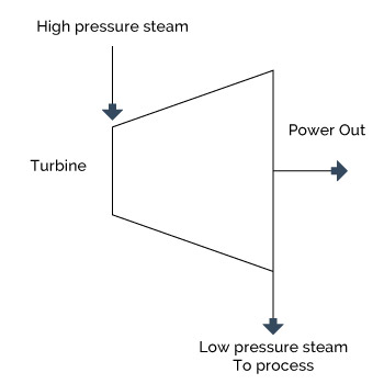
Figure 4-11: Non-Condensing (Back-Pressure) Steam Turbine
4.5.3.1 Non-Condensing
(Back-pressure) Turbine
The non-condensing turbine (also referred to as a back-pressure turbine) exhausts its entire flow of steam to the industrial process or facility steam mains at conditions close to the process heat requirements, as shown in Figure 4-11.
Usually, the steam sent into the mains is not much above saturation temperature. The term “back-pressure” refers to turbines that exhaust steam at atmospheric pressures and above. The discharge pressure is established by the specific CHP application. 50, 150 and 250 psig are the most typical pressure levels for steam distribution systems. The lower pressures are most often used in small and large district heating systems, and the higher pressures most often used in supplying steam to industrial processes. Industrial processes often include further expansion for mechanical drives, using small steam turbines for driving heavy equipment that is intended to run continuously for very long periods. Significant power generation capability is sacrificed when steam is used at appreciable pressure rather than being expanded to vacuum in a condenser. Discharging steam into a steam distribution system at 150 psig can sacrifice slightly more than half the power that could be generated when the inlet steam conditions are 750 psig and 800° F, typical of small steam turbine systems.
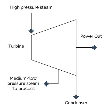
Figure 4-12: Extraction Steam Turbine
4.5.3.2 Extraction Turbine
The extraction turbine has opening(s) in its casing for extraction of a portion of the steam at some intermediate pressure. The extracted steam may be use for process purposes in a CHP facility, or for feedwater heating as is the case in most utility power plants. The rest of the steam is condensed, as illustrated in Figure 4-12.
Figure 4-12: Extraction Steam Turbine
The steam extraction pressure may or may not be automatically regulated depending on the turbine design. Regulated extraction permits more steam to flow through the turbine to generate additional electricity during periods of low thermal demand by the CHP system. In utility type steam turbines, there may be several extraction points, each at a different pressure corresponding to a different temperature at which heat is needed in the thermodynamic cycle. The facility’s specific needs for steam and power over time determine the extent to which steam in an extraction turbine will be extracted for use in the process, or be expanded to vacuum conditions and condensed in a condenser.
In large, often complex, industrial plants, additional steam may be admitted (flows into the casing and increases the flow in the steam path) to the steam turbine. Often this happens when multiple boilers are used at different pressure, because of their historical existence. These steam turbines are referred to as admission turbines. At steam extraction and admission locations there are usually steam flow control valves that add to the steam and control system cost.
There are numerous mechanical design features that have been created to increase efficiency, provide for operation over a range of conditions, simplify manufacture and repair, and achieve other practical purposes. The long history of steam turbine use has resulted in a large inventory of steam turbine stage designs that can be used to tailor a product for a specific application. For example, the division of steam acceleration and change in direction of flow varies between competing turbine manufacturers under the identification of impulse and reaction designs. Manufacturers tailor clients’ design requests by varying the flow area in the stages and the extent to which steam is extracted (removed from the flow path between stages) to accommodate the specification of the client.
When steam is expanded through a very high pressure ratio, as in utility and large industrial steam systems, the steam can begin to condense in the turbine when the temperature of the steam drops below the saturation temperature at that pressure. If water drops were allowed to form in the turbine, blade erosion would occur when the drops impact on the blades. At this point in the expansion the steam is sometimes returned to the boiler and reheated to high temperature and then returned to the turbine for further (safe) expansion. In a few very large, very high pressure, utility steam systems double reheat systems are installed.
With these choices the designers of the steam supply system and the steam turbine have the challenge of creating a system design which best delivers the (seasonally varying) power and steam demands.
Between power (only) output of a condensing steam turbine and the power and steam combination of a back pressure steam turbine, essentially any ratio of power to heat output can be supplied to a facility. Back-pressure steam turbines can be obtained with a variety of back- pressures controls, further increasing the variability of the power-to-heat ratio.
4.5.4 Steam Turbine Design Characteristics
Custom design: Steam turbines can be designed to match CHP design pressure and temperature requirements. The steam turbine can be designed to maximize electric efficiency while providing the desired thermal output.
Thermal output: Steam turbines are capable of operating over a very broad range of steam pressures. Utility steam turbines operate with inlet steam pressures up to 3500 psig and exhaust vacuum conditions as low as one inch of Hg (absolute). Steam turbines can be custom designed to deliver the thermal requirements of the CHP applications through the use of back-pressure or extraction steam at appropriate pressures and temperatures.
Fuel flexibility: Steam turbines offer a wide range of fuel flexibility using a variety of fuel sources in the associated boiler or other heat source, including coal, oil, natural gas, wood, and waste products.
Reliability and life: Steam turbine life is extremely long. There are steam turbines that have been in service for over 50 years. Overhaul intervals are measured in years. When properly operated and maintained (including proper control of boiler water chemistry), steam turbines are extremely reliable. They require controlled thermal transients as the massive casing heats up slowly and differential expansion of the parts must be minimized.
Size range: Steam turbines are available in sizes from under 100 kW to over 250 MW. In the multi-megawatt size range, industrial and utility steam turbine designations merge, with the same turbine (high pressure section) able to serve both industrial and small utility applications.
Emissions: Emissions are dependent upon the fuel used by the boiler or other steam source, the boiler furnace combustion section design and operation, and any built-in and add-on boiler exhaust cleanup systems.
Electrical Efficiency: The electrical generating efficiency of steam turbine power plants varies from a high of 36% HHV for large, electric utility plants designed for the highest practical annual capacity factor, to under 10% HHV for small, simple plants which make electricity as a byproduct of delivering steam to industrial processes or district heating systems for colleges, industrial parks and building complexes. Steam turbine thermodynamic efficiency (isentropic efficiency) refers to the ratio of power actually generated from the turbine to what would be generated by a perfect turbine with no internal losses using steam at the same inlet conditions and discharging to the same downstream pressure. Turbine thermodynamic efficiency is not to be confused with electrical generating efficiency, which is the ratio of net power generated to total fuel input to the cycle. Steam turbine thermodynamic efficiency is a measure of how efficiently the turbine extracts power from the steam itself and is useful in identifying the conditions of the steam as it exhausts from the turbine and in comparing the performance of various steam turbines. Multistage (moderate to high pressure ratio) steam turbines have thermodynamic efficiencies that vary from 65% for very small (under 1,000 kW) units to over 90% for large industrial and utility sized units. Small, single stage steam turbines can have efficiencies as low as 50%.
CHP System Efficiency : Steam turbine CHP systems are generally characterized by very low power to heat ratios, typically in the 0.05 to 0.2 range. This is because electricity is a byproduct of heat generation, with the system optimized for steam production. Hence, while steam turbine CHP system electrical efficiency may seem very low, it is because the primary objective is to produce large amounts of steam. The effective electrical efficiency of steam turbine systems, however, is generally very high, because almost all the energy difference between the high pressure boiler output and the lower pressure turbine output is converted to electricity. This means that total CHP system efficiencies are generally very high and approach the boiler efficiency level. Steam boiler efficiencies range from 70 to 85 % HHV depending on boiler type and age, fuel, duty cycle, application, and steam conditions.
4.5.5 Process Steam and Performance Tradeoffs
Heat recovery methods from a steam turbine use back pressure exhaust or extraction steam. However, the term is somewhat misleading, since in the case of steam turbines, it is the steam turbine itself that can be defined as a heat recovery device.
The amount and quality of recovered heat is a function of the entering steam conditions and the design of the steam turbine. Exhaust steam from the turbine can be used directly in a process or for district heating. It can also be converted to other forms of thermal energy, including hot or chilled water. Steam discharged or extracted from a steam turbine can be used in a single- or double effect absorption chiller. The steam turbine can also be used as a mechanical drive for a centrifugal chiller.
4.5.6 Performance and Efficiency Enhancements
In industrial steam turbine systems, business conditions determine the requirements and relative values of the electric power and the process steam. Plant system engineers then decide the extent of efficiency enhancing options to incorporate in terms of their incremental effects on performance and plant cost, and select appropriate steam turbine inlet and exhaust conditions. Often the steam turbine is going into a system that already exists and is being modified, so that a number of steam system design parameters are already determined by previous decisions, which exist as system hardware characteristics.
As the stack temperature of the boiler exhaust combustion products still contain some heat, tradeoffs are made regarding the extent of investment in heat reclamation equipment for the sake of efficiency improvement. Often the stack exhaust temperature is set at a level where further heat recovery would result in condensation of corrosive chemical species in the stack, with consequential deleterious effects on stack life and safety.
4.5.7 Capital Cost
A steam turbine-based CHP plant is a complex process with many interrelated subsystems that must usually be custom designed. A typical breakdown of installed costs for a steam turbine CHP plant is 25% – boiler, 20% – fuel handling, storage and preparation system, 20% – stack gas cleanup and pollution controls, 15% steam turbine generator, and 20% – field construction and plant engineering. Boiler costs are highly competitive. Typically, the only area in which significant cost reductions can be made when designing a system is in fuel
handling/storage/preparation.
In a steam turbine cogeneration plant, especially one burning solid fuel such as biomass, the turbine accounts for a much smaller portion of total system installed costs than is the case with internal combustion engines and industrial gas turbines. A typical coal/wood fired boiler costs more than the steam turbine. The cost of complete solid fuel cogeneration plants varies with many factors, with fuels handling, pollution control equipment and boiler cost all being major cost items. Because of both the size of such plants and the diverse sources of the components, solid fuel cogeneration plants invariably involve extensive system engineering and field labor during construction. Typical complete plant costs run well over $1,000/kW, with little generalization except that for the same fuel and configuration, costs per kW of capacity generally increase as size decreases.
Steam turbine costs exhibit a modest extent of irregularity, as steam turbines are made in sizes with finite steps between the sizes. The cost of the turbine is generally the same for the upper and lower limit of the steam flowing through it, so step-like behavior is sometimes seen in steam turbine prices. Since they come in specific size increments, a steam turbine that is used at the upper end of its range of power capability costs less per kW generated than one that is used at the lower end of its capability. Additionally, raw material cost, local labor rates, delivery times, availability of existing major components and similar business conditions can affect steam turbine pricing.
Often steam turbines are sold to fit into an existing plant. In some of these applications, the specifications, mass flow, pressure, temperature, and back-pressure or extraction conditions are not conditions for which there exists a large amount of demand. These somewhat unique machines are more expensive per kilowatt than machines that are in greater demand. Three reasons can be given: 1) a greater amount of custom engineering and manufacturing setup may be required; 2) there is less potential for sales of duplicate or similar units; and 3) there are fewer competitive bidders. The truly competitive products are the “off-the-rack” type machines, while “custom” machines are naturally more expensive.
Steam turbine prices vary greatly with the extent of competition and related manufacturing volumes for units of desired size, inlet and exit steam conditions, rotational speed and standardization of construction. Prices are usually quoted for an assembled steam turbine-electrical generator package. The electrical generator can account for 20% to 40% of the assembly. As the steam turbine/electrical generator package is heavy, due in large part to the heavy walled construction of the high pressure turbine casing, it must be mounted carefully on an appropriate pedestal. The installation and connection to the boiler through high pressure-high temperature steam pipes must be performed with engineering and installation expertise. As the high pressure steam pipes typically vary in temperature by 750° F between cold standby/repair status and full power status, care must be taken in installing a means to accommodate the differential expansion accompanying startup and shutdown. Should the turbine have variable extraction, the cost of the extraction valve and control system adds to the installation.
Small steam turbines are, to a varying degree, custom produced products rather than standard products. This both adds cost and makes costs more variable. They are manufactured by several international manufacturers in the industrial sizes where demand is appreciable. Business is competitive in these sizes. Small steam turbines, below about 2 MW, have a relatively small market. In these small sizes there is less competition and lower manufacturing volume, so that component costs are not as competitive, the economies of scale in both size and manufacturing volumes disfavor such small sizes, and the fraction of total cost due to system engineering and field construction are high.
Since steam for a steam turbine is generated in a boiler by combustion and heat transfer, the pressure and temperature of the steam is limited by furnace heat transfer designs, manufacturing considerations, and boiler tube bundle designs. Higher heat fluxes in the boiler enable more compact boiler designs with less boiler tube material. However, higher heat fluxes also result in higher boiler tube temperatures and the need for the use of higher-grade (adequate strength at higher temperature) boiler tube materials. Such engineering economic tradeoffs between temperature (with consequential increases in efficiency) and cost appear throughout the steam plant.
In contrast to the temperature limitations on boiler tubes, which are exposed to high temperatures and heat fluxes in the furnace, steam turbine material selection is easier. However, an often-overlooked component in the steam power system is the steam (safety) stop valve, which is immediately ahead of the steam turbine and is designed for full load at the temperature and pressure of the steam supply. This safety valve is necessary because if the generator electric load were lost (an occasional occurrence), the turbine would rapidly overspeed and destroy itself. Other accidents are possible, supporting the need for the turbine stop valve, which adds significant cost to the system.
4.5.8 Maintenance
Steam turbines are very rugged units, with operational life often exceeding 50 years. Maintenance is simple, comprised mainly of making sure that all fluids (steam flowing through the turbine and the oil for the bearing) are always clean and at the proper temperature. The oil lubrication system must be clean and at the correct operating temperature and level to maintain proper performance. Other items include inspecting auxiliaries such as lubricating-oil pumps, coolers and oil strainers and checking safety devices such as the operation of over-speed trips.
In order to obtain reliable service, steam turbines require long warm-up periods so that there are minimal thermal expansion stress and wear concerns. Steam turbine maintenance costs are quite low, typically less than $0.004 per kWh. Boilers and any associated solid fuel processing and handling equipment that is part of the boiler/steam turbine plant require their own types of maintenance.
One maintenance issue with steam turbines is solids carry over from the boiler. These solids deposits on turbine nozzles and other internal parts and degrades turbine efficiency and power output. Some of these are water soluble but others are not. Three methods are employed to remove such deposits: 1) manual removal; 2) cracking off deposits by shutting the turbine off and allowing it to cool; and 3) for water soluble deposits, water washing while the turbine is running.
4.5.9 Fuels
Industrial boilers operate on a wide variety of fuels, including wood, coal, natural gas, oils (including residual oil, the left-over material when the valuable distillates have been separated for sale), municipal solid wastes, and sludges. The fuel handling, storage and preparation equipment needed for solid fuels adds considerably to the cost of an installation. Thus, such fuels are used only when a high annual capacity factor is expected of the facility, or when the solid material has to be disposed of to avoid an environmental or space occupancy problem.
4.5.10 Availability
Steam turbines are generally considered to have 99% plus availability with longer than one year between shutdowns for maintenance and inspections. This high level of availability applies only to the steam turbine, not the boiler or HRSG that is supplying the steam.
4.5.11 Emissions and Control
Emissions associated with a steam turbine are dependent on the source of the steam. Steam turbines can be used with a boiler firing any one or a combination of a large variety of fuel sources, or they can be used with a gas turbine in a combined cycle configuration. Boiler emissions vary depending on fuel type and environmental conditions.
Boilers emissions include nitrogen oxide (NO x ), sulfur oxides (SO x ), particulate matter (PM), carbon monoxide (CO), and carbon dioxide (CO 2 ). Recently NO x control has been the primary focus of emission control research and development in boilers. The following provides a description of the most prominent emission control approaches.
Combustion control techniques are less costly than post-combustion control methods and are often used on industrial boilers for NO x control. Control of combustion temperature has been the principal focus of combustion process control in boilers. Combustion control requires tradeoffs – high temperatures favor complete burn-up of the fuel and low residual hydrocarbons and CO, but promote NO x formation. Very lean combustion dilutes the combustion process and reduces combustion temperatures and NO x formation. However, if the mixture is too lean, incomplete combustion occurs, increasing CO and VOC emissions.
4.5.11.1 Flue Gas Recirculation (FGR)
FGR is one technique for reducing NO x emissions from industrial boilers with inputs below 100 MMBtu/hr. With FGR, a portion of the relatively cool boiler exhaust gases re-enter the combustion process, reducing the flame temperature and associated thermal NO x formation. It is an effective NO x reduction method for firetube and watertube boilers, and many applications can rely solely on FGR to meet environmental standards.
External FGR employs a fan to recirculate the flue gases into the flame, with external piping carrying the gases from the stack to the burner. A valve, responding to boiler input, controls the recirculation rate. Induced FGR relies on the combustion air fan for flue gas recirculation. In this scheme, a portion of the gases travel via ductwork or internally to the air fan, where they are premixed with combustion air and introduced into the flame through the burner. Induced FGR in newer designs utilize an integral design that is relatively uncomplicated and reliable.
Generally the limit for NOx reduction via FGR is 80% in natural gas-fired boilers and 25% for standard fuel oils
4.5.11.2 Low Excess Air Firing (LEA)
Boilers are fired with excess air to ensure complete combustion. However, high excess air levels can result in increased NO x formation, because the excess nitrogen and oxygen in the combustion air entering the flame combine to form thermal NO x . Firing with low excess air means limiting the amount of excess air that enters the combustion process, thus limiting the amount of extra nitrogen and oxygen entering the flame. This is accomplished through burner design modification and is optimized through the use of oxygen trim controls.
LEA typically results in overall NOx reductions of 5 to 10% when firing with natural gas, and is suitable for most boilers.
4.5.11.3 Low Nitrogen Fuel Oil
NO x formed by fuel-bound nitrogen can account for 20 to 50% of total NO x levels in oil-fired boiler emissions. The use of low nitrogen fuels in boilers firing distillate oils is one method of reducing NO x emissions. Such fuels can contain up to 20 times less fuel-bound nitrogen than standard No. 2 oil. NO x reductions of up to 70% over NO x emissions from standard No. 2 oils have been achieved in firetube boilers utilizing flue gas recirculation.
4.5.11.4 Burner Modifications
By modifying the design of standard burners to achieve pre-mixed combustion, lower and more uniform flame temperatures, and internal flue gas recirculation, lower overall NO x emissions can be obtained, often at a low cost premium. While most boiler types and sizes can accommodate burner modifications, it is most effective for boilers firing natural gas and distillate fuel oils, with less effectiveness in heavy oil-fired boilers. Also, burner modifications may be complemented with other NO x reduction methods, such as flue gas recirculation, to comply with some of the more stringent environmental regulations. Low NO x burner designs can adversely impact boiler operating parameters such as stability, turndown, capacity, CO levels and efficiency. New burner designs entering the market have been able to eliminate or minimize these adverse impacts.
4.5.11.5 Water/Steam Injection
Injecting water or steam into the flame reduces flame temperature, lowering thermal NO x formation and overall NO x emissions. However, under normal operating conditions, water/steam injection can lower boiler efficiency by 3 to 10%. Also, there is a practical limit to the amount that can be injected without causing condensation-related problems. This method is often employed in conjunction with other NO x control techniques such as burner modifications or flue gas recirculation. When used with natural gas-fired boilers, water/steam injection can result in NO x reduction of up to 80%, with lower reductions achievable in oil-fired boilers.
4.5.11.6 Selective Non-Catalytic Reduction (SNCR)
In boiler SNCR, a NO x reducing agent such as ammonia or urea is injected into the boiler exhaust gases at a temperature in the 1,400 to 1,600° F range. The agent breaks down the NO x in the exhaust gases into water and atmospheric nitrogen (N 2 ). While NSCR can reduce boiler NO x emissions by up to 70%, it is very difficult to apply to industrial boilers that modulate or cycle frequently because to perform properly, the agent must be introduced at a specific flue gas temperature. Also, the location of the exhaust gases at the necessary temperature is constantly changing in a cycling boiler.
4.5.11.7 Selective Catalytic Reduction (SCR)
This technology involves the injection of the reducing agent into the boiler exhaust gas in the presence of a catalyst. The catalyst allows the reducing agent to operate at lower exhaust temperatures than NSCR, in the 500 to 1,200° F depending on the type of catalyst. NO x reductions of up to 90% are achievable with SCR. The two agents used commercially are ammonia (NH 3 in anhydrous liquid form or aqueous solution) and aqueous urea. Urea decomposes in the hot exhaust gas and SCR reactor, releasing ammonia. Approximately 0.9 to 1.0 moles of ammonia is required per mole of NO x at the SCR reactor inlet in order to achieve an 80 to 90% NO x reduction. SCR is however costly to use and can only occasionally be justified on boilers with inputs of less than 100 MMBtu/hr. SCR requires on-site storage of ammonia, a hazardous chemical. In addition, ammonia can “slip” through the process unreacted, contributing to environmental health concerns.
4.5.12 Organic Rankine Cycle
The Rankine cycle is a thermodynamic cycle used to generate electricity in many power stations. Superheated steam is generated in a boiler, and then expanded in a steam turbine. The turbine drives a generator, to convert the work into electricity. The remaining steam is then condensed and recycled as feedwater to the boiler.
Organic substances can be substituted for steam when temperatures are limited to less than 750 degree Fahrenheit. This is called an Organic Rankine Cycle (ORC).
ORC can make use of low temperature waste heat to generate electricity. At these low temperatures a steam cycle would be inefficient, due to enormous volumes of low pressure steam, causing very voluminous and costly plants. ORCs can be applied for low temperature waste heat recovery (industry), efficiency improvement in onsite power generation, and recovery of geothermal and solar heat.
Several organic compounds have been used in ORCs (e.g. refrigerants, iso-pentane or ammonia) to match the temperature of the available waste heat. Waste heat temperatures can be as low as 150 ° F. The efficiency of an ORC is estimated to be between 10 and 20%, depending on temperature levels. On many sites no suitable use is available for low temperature waste heat, hence upgrading by the use of a heat pump (or transformer) or an ORC are good energy recovery candidates. Figure 4-13 below shows a typical ORC where waste heat (1) evaporates the refrigerant which passes through the turbine producing power (2). The refrigerant is then condensed (3) and pumped back to the waste heat source (4). The system utilizes a closed-loop Rankine cycle using an advanced refrigerant.
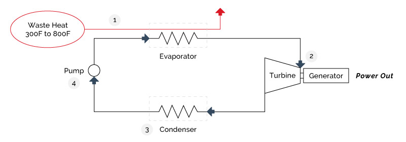
Figure 4-13: Organic Rankine Cycle Courtesy of UT Power
- At 80° F, the vapor pressure of water is 0.51 psia, at 100° F it is 0.95 psia, at 120° F it is 1.69 psia and at 140° F Fahrenheit it is 2.89 psia
- From a reference condition of condensation at 100 Fahrenheit, 6.5% less power is obtained from the inlet steam when the temperature at which the steam is condensed is increased (because of higher temperature ambient conditions) to 115 F. Similarly the power output is increased by 9.5% when the condensing temperature is reduced to 80 Fahrenheit. This illustrates the influence of steam turbine discharge pressure on power output and, consequently, net heat rate (and efficiency.)
- At 50 psig (65 psia) the condensation temperature is 298° F, at 150 psig (165 psia) the condensation temperature is 366° F, and at 250 psig (265 psia) it is 406° F.
- All turbine and engine manufacturers quote heat rates in terms of the lower heating value (LHV) of the fuel. However, the usable energy content of fuels is typically measured on a higher heating value basis (HHV). In addition, electric utilities measure power plant heat rates in terms of HHV. For natural gas, the average heat content of natural gas is 1,030 Btu/scf on an HHV basis and 930 Btu/scf on an LHV basis – or about a 10%
difference . - Net power output / total fuel input into the system.
- (Steam turbine electric power output)/(Total fuel into boiler – (steam to process/boiler efficiency))
- Net power and steam generated divided by total fuel input
- Spiewak and Weiss, loc. Cit., pages 82 and 95. These figures are for a 32.3 MW multi-fuel fired, 1,250 psig, 900° F, 50 psig backpressure steam turbine used in an industrial cogeneration plant
- Data on steam generator costs shows cost increasing with decreasing size, with a 5.25 MW, 900 psig, 850 ° F, 125 psig backpressure steam turbine/generator costing $285/kw (installed). In that installation the boiler alone, excluding fuel handling and pollution control equipment, cost 150% of the cost of the steam turbine