
4. CHP Technologies
This chapter characterizes the prime mover technologies typically used in CHP applications. The characterizations include reciprocating engines, microturbines, gas turbines, steam turbines, and fuel cells. Historically the primary industrial technologies are gas turbines, reciprocating engines and steam turbines. Conventional large industrial systems are relatively widely deployed and utilize readily available thermal technologies.
Even though the commercial sector is about 75% as large as the industrial sector in terms of electricity demand, the existing applications of CHP are nine times larger in the industrial sector. There are viable CHP opportunities in the commercial sector, but technology and application matching in the commercial sector is more difficult:
- On average, commercial sites are much smaller than industrial sites. Technologies for smaller applications have been more expensive and less efficient than larger CHP.
- Commercial establishments generally operate fewer hours per year and have lower load factors, providing fewer hours of operation per year in which to payback their higher first costs.
Unlike the majority of industrial projects that can absorb the entire thermal output of a CHP system onsite, many commercial sites have either an inadequate thermal load or a highly seasonal load such as space heating. The best overall efficiency and economics come from a steady thermal load. These loads are concentrated in relatively few types of commercial applications. These have been the focus of the traditional commercial/institutional CHP market (e.g., education, hospitals, and hotels).
4.1 Reciprocating Engines
Reciprocating internal combustion engines are a widespread and well-known technology. Worldwide production for reciprocating internal combustion engines is over 200 million units per year. This includes both diesel and spark ignition configurations and they are important for both transportation and stationary uses. The long history of technical development and high production levels have contributed to making reciprocating engines a rugged, reliable, and economic choice as a prime mover for CHP applications.
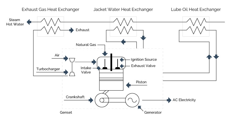
Figure 4-1: Reciprocating Engine System
Reciprocating engine technology has improved dramatically over the past three decades, driven by economic and environmental pressures for power density improvements (more output per unit of engine displacement), increased fuel efficiency and reduced emissions. Computer systems have greatly advanced reciprocating engine design and control, accelerating advanced engine designs and making possible more precise control and diagnostic monitoring of the engine process. Stationary engine manufacturers and worldwide engine R&D firms continue to drive advanced engine technology, including accelerating the diffusion of technology and concepts from the automotive market to the stationary market.
4.1.1 Technology Description
There are two primary reciprocating engine designs relevant to stationary power generation applications – the spark ignition Otto-cycle engine and the compression ignition Diesel-cycle engine. The essential mechanical components of the Otto-cycle and Diesel-cycle are the same. The primary difference between the Otto and Diesel cycles is the method of igniting the fuel. Spark ignition engines (Otto-cycle) use a spark plug to ignite a pre-mixed air fuel mixture introduced into the cylinder. Compression ignition engines (Diesel-cycle) compress the air introduced into the cylinder to a high pressure, raising its temperature to the auto-ignition temperature of the fuel which is injected at high pressure.
There are 2-cycle engines in stationary power applications, particularly in standby service. However, most spark ignition and the diesel engines relevant to stationary power generation applications complete a power cycle in four strokes of the piston within the cylinder.
- Intake stroke – introduction of air (diesel) or air-fuel mixture (spark ignition) into the cylinder
- Compression stroke – compression of air or an air-fuel mixture within the cylinder. In diesel engines, the fuel is injected at or near the end of the compression stroke (top dead center or TDC), and ignited by the elevated temperature of the compressed air in the cylinder. In spark ignition engines, the compressed airfuel mixture is ignited by an ignition source at or near TDC
- Power stroke – acceleration of the piston by the expansion of the hot, high pressure combustion gases
- Exhaust stroke – expulsion of combustion products from the cylinder through the exhaust port
The simplest natural gas engines operate with natural aspiration of air and fuel into the cylinder (via a carburetor or other mixer) by the suction of the intake stroke. High performance natural gas engines are turbocharged to force more air into the cylinders. Natural gas spark ignition engines operate at modest compression ratios (compared with diesel engines) in the range of 9:1 to 12:1 depending on engine design and turbocharging. Modest compression is required to prevent auto-ignition of the fuel and engine knock, which can cause serious engine damage.
Using high energy ignition technology, very lean fuel-air mixtures can be burned in natural gas engines, lowering peak temperatures within the cylinders and resulting in reduced NO x emissions. The lean burn approach in reciprocating engines is analogous to dry low-NO x combustors in gas turbines. All major natural gas engine manufacturers offer lean burn, low emission models and are engaged in R&D to further improve their performance.
Natural gas spark ignition engine efficiencies are typically lower than diesel engines because of their lower compression ratios. However, large, high performance lean burn engine efficiencies approach those of diesel engines of the same size. Natural gas engine efficiencies range from about 28% (LHV) for small engines (<50 kW) to 46% (LHV) for the largest high performance, lean burn engines.
Dual fuel engines are predominantly fueled by natural gas with a small percentage of diesel oil added. There are two main configurations for introducing the gaseous fuel in a dual fuel engine. These engines can be purpose built or conversions of diesel engines. Such engines can be switched to 100% diesel operation. Dual fuel engines provide a multi-use functionality. Operation on predominantly cheaper and cleaner burning natural gas allows the engine to be used in CHP and peak shaving applications, while operation on 100% diesel allows the engine to also meet the onsite fuel requirements of emergency generators. The dual function adds benefit in applications that have specific emergency generator requirements such as in hospitals or in public buildings.
There are three main configurations for introducing the gaseous and pilot diesel fuel:
- Low pressure injection with the intake air
- High pressure injection after the intake air has been compressed by the piston
- Micropilot pre-chamber introduction of the diesel fuel.
New dual-fuel engines are offered in oil and gas production markets to reduce operating costs. Dual-fuel retrofits of existing diesel engines are also offered as a means to reduce both operating costs and emissions for extending the hours of use for limited duty engines such as emergency and peaking applications. Dual fuel is not widely used for CHP applications.
4.1.2 Performance
Table 4-1 summarizes performance characteristics for typical commercially available natural gas spark ignition engine CHP systems over a 100 kW to 9 MW size range. This size range covers the majority of the market applications for engine-driven CHP. Heat rates and efficiencies shown were taken from manufacturers’ specifications and industry publications. Available thermal energy was taken directly from vendor specifications or, if not provided, calculated from published engine data on engine exhaust temperatures and engine jacket and lube system coolant flows. CHP thermal recovery estimates are based on producing hot water for process or space heating needs.
Most reciprocating engine manufacturers typically assign three power ratings to engines depending on the intended load service:
- Standby – continuous full or cycling load for a relatively short duration (usually less than 100 hours) – maximum power output rating
- Prime – continuous operation for an unlimited time (except for normal maintenance shutdowns), but with regular variations in load – 80 to 85% of the standby rating
- Baseload – continuous full-load operation for an unlimited time (except for normal maintenance shutdowns) – 70 to 75% of the standby rating
The ratings shown here are for baseload operation.
Table 4-1. Gas Spark Ignition Engine CHP – Typical Performance Parameters
| Cost and Performance Characteristics | System | System | System | System | System |
|---|---|---|---|---|---|
| 1 | 2 | 3 | 4 | 5 | |
| Baseload Electric Capacity (kW) | 100 | 633 | 1,121 | 3,326 | 9,341 |
| Total Installed Cost in 2013 ($/kW) | $2,900 | $2,837 | $2,366 | $1,801 | $1,433 |
| Electrical Heat Rate (Btu/kWh), HHV | 12,637 | 9,896 | 9,264 | 8,454 | 8,207 |
| Electrical Efficiency (%), HHV | 27.0% | 34.5% | 36.8% | 40.4% | 41.6% |
| Engine Speed (rpm) | 2,500 | 1,800 | 1,800 | 1,500 | 720 |
| Fuel Input (MMBtu/hr), HHV | 1.26 | 6.26 | 10.38 | 28.12 | 76.66 |
| Required Fuel Gas Pressure (psid) | 0.4-1.0 | >1.16 | >1.74 | >1.74 | 75 |
| CHP Characteristics | |||||
| Exhaust Flow (1000 lb/hr) | 1.2 | 7.89 | 13.68 | 40.17 | 120 |
| Exhaust Temperature (Fahrenheit) | 1,200 | 941 | 797 | 721 | 663 |
| Heat Recovered from Exhaust (MMBtu/hr) | 0.21 | 1.48 | 2 | 5.03 | 10 |
| Heat Recovered from Cooling Jacket (MMBtu/hr) | 0.46 | 0.72 | 1.29 | 1.63 | 4.27 |
| Heat Recovered from Lube System (MMBtu/hr) | Incl. | 0.27 | 0.44 | 1.12 | 5.0 |
| Heat Recovered from Intercooler (MMBtu/hr) | n/a | 0.31 | 0.59 | 2.89 | 7.54 |
| Total Heat Recovered (MMBtu/hr) | 0.67 | 2.78 | 4.32 | 10.67 | 26.81 |
| Total Heat Recovered (kW) | 196 | 815 | 1,266 | 3.126 | 7,857 |
4.1.3 Emissions
Emissions of criteria pollutantss are the primary environmental concern with reciprocating engines. The primary pollutants are oxides of nitrogen (NO x), carbon monoxide (CO), and volatile organic compounds (VOCs – unburned, non-methane hydrocarbons) with reciprocating engines operating on natural gas. Emissions of sulfur compounds, primarily SO 2, are related to the sulfur content of the fuel. Engines operating on natural gas or distillate oil, which has been desulfurized in the refinery, emit insignificant levels of SO x. In general, SO x emissions are an issue only in large, slow speed diesels firing heavy oils. Particulate matter (PM) can be an important pollutant for engines using liquid fuels. Ash and metallic additives in the fuel contribute to PM in the exhaust. Particulate emissions from 4-stroke lean burn natural gas engines are 4,000 times lower than for an uncontrolled diesel engine.
NO x emissions are usually the primary concern with natural gas engines and are a mixture of (mostly) NO and NO 2 in variable composition. Among natural gas engine options, lean burn natural gas engines produce the lowest NO x emissions directly from the engine.
There are several types of catalytic exhaust gas treatment processes that are applicable to various types of reciprocating engines – three-way catalyst, selective catalytic reduction, and oxidation catalysts.
The three-way conversion process (TWC) is the basic automotive catalytic converter process that reduces concentrations of all three criteria pollutants. The TWC is also called non-selective Catalytic Reduction (NSCR). In a properly controlled TWC system, NO x and CO reductions are generally greater than 90% and VOCs are reduced about 80%. TWCs are only effective in rich-burning engines.
Lean burn engines equipped with selective catalytic reduction (SCR) technology selectively reduces NO x to N 2 in the presence of a reducing agent. NO x reductions of 80 to 90% are achievable with SCR. Higher reductions are possible with the use of more catalyst or more reducing agent, or both. The two agents used commercially are ammonia (NH 3 in anhydrous liquid form or aqueous solution) and aqueous urea. Urea decomposes in the hot exhaust gas and SCR reactor, releasing ammonia.
SCR systems add a significant cost burden to the installation cost and maintenance cost of an engine system, and can severely impact the economic feasibility of smaller engine projects. Oxidation catalysts generally are precious metal compounds that promote oxidation of CO and hydrocarbons to CO 2 and H 2 O in the presence of excess O2. CO and NMHC conversion levels of 98 to 99% are achievable. Methane conversion may approach 60 to 70%. Oxidation catalysts are now widely used with all types of engines, including diesel engines. They are being used increasingly with lean burn gas engines to reduce their relatively high CO and hydrocarbon emissions.
4.1.4 CHP Applications
Reciprocating engines are well suited to a variety of distributed generation applications, and are used throughout industrial, commercial, and institutional facilities for power generation and CHP. Reciprocating engines start quickly, follow load well, have good part load efficiencies, and generally have high reliabilities. In many cases, having multiple reciprocating engine units further increases overall plant capacity and availability. Reciprocating engines have higher electrical efficiencies than gas turbines of comparable size, and thus lower fuel-related operating costs. In addition, the upfront costs of reciprocating engine gensets are generally lower than gas turbine gensets in sizes below 20 MW. Reciprocating engine maintenance costs are generally higher than comparable gas turbines, but the maintenance can often be handled by in-house staff or provided by local service organizations.
4.1.5 Thermal Energy Generation
The economics of engines in on-site power generation applications often depend on effective use of the thermal energy contained in the exhaust gas and cooling systems, which generally represents 60 to 70 % of the inlet fuel energy. Most of the waste heat is available in the engine exhaust and jacket coolant, while smaller amounts can be recovered from the lube oil cooler and the turbocharger’s intercooler and aftercooler (if so equipped). As shown in the previous table, 45 to 55% of the waste heat from engine systems is recovered from jacket cooling water and lube oil cooling systems at a temperature too low to produce steam. This feature is generally less critical in commercial/institutional applications where it is more common to have hot water thermal loads. Steam can be produced from the exhaust heat if required (maximum pressure of 400 psig), but if no hot water is needed, the amount of heat recovered from the engine is reduced and total CHP system efficiency drops accordingly.
Heat in the engine jacket coolant accounts for up to 30% of the energy input and is capable of producing 190 to 230° F hot water. Some engines, such as those with high pressure or ebullient cooling systems, can operate with water jacket temperatures of up to 265° F. Engine exhaust heat represents 30 to 50% of the available waste heat. Exhaust temperatures for the example systems range from 720 to 1000° F. By recovering heat in the cooling systems and exhaust, around 80% of the fuel’s energy can be effectively utilized to produce both power and useful thermal energy.
The most common method of recovering engine heat is the closed-loop cooling system as shown in Figure 4-2. These systems are designed to cool the engine by forced circulation of a coolant through engine passages and an external heat exchanger. An excess heat exchanger transfers engine heat to a cooling tower or a radiator when there is excess heat generated. Closed-loop water cooling systems can operate at coolant temperatures from 190 to 250° F. Depending on the engine and CHP system’s requirements, the lube oil cooling and turbocharger after cooling may be either separate or part of the jacket cooling system.
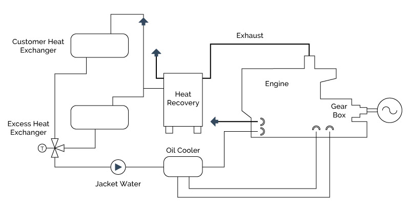
Figure 4-2: Closed-Loop Heat Recovery
Ebullient cooling systems cool the engine by natural circulation of a boiling coolant through the engine. This type of cooling system is typically used in conjunction with exhaust heat recovery for production of low-pressure steam.
The coolant at the engine outlet is maintained at saturated steam conditions and is usually limited to 250°F and a maximum of 15 psig. Inlet cooling water is also near saturation conditions and is generally 2 to 3°F below the outlet temperature. The uniform temperature throughout the coolant circuit extends engine life and contributes to improved combustion efficiencies.
Exhaust heat recovery can be independent of the engine cooling system or coupled with it. In a typical district heating system, jacket cooling, lube oil cooling, single stage aftercooling and exhaust gas heat recovery are all integrated for steam production.
4.1.6 Current Market Applications
There are over 2,000 active reciprocating engine combined heat and power (CHP) installations in the US providing nearly 2.3 gigawatts (GW) of power capacity. These systems are predominantly spark ignition engines fueled by natural gas and other gaseous fuels (biogas, landfill gas). Natural gas is lower in cost than petroleum based fuels and emissions control is generally more effective using gaseous fuels. Reciprocating engine CHP systems are commonly used in universities, hospitals, water treatment facilities, industrial facilities, and commercial and residential buildings. Facility capacities range from 30 MW to 30 MS, with many larger facilities comprised of multiple units. Spark ignited engines fueled by natural gas or other gaseous fuels represent 84% of the installed reciprocating engine CHP capacity.
Thermal loads most amenable to engine-driven CHP systems in commercial/institutional buildings are space heating and hot water requirements. The simplest thermal load to supply is hot water. Primary applications for CHP in the commercial/institutional sectors are those building types with relatively high and coincident electric and hot water demand such as colleges and universities, hospitals and nursing homes, and lodging. Office buildings, and certain warehousing and mercantile/service applications can be economic applications for CHP if space heating or cooling needs can be incorporated.
A typical commercial application for reciprocating engine CHP is a hospital or health care facility with a 1 MW CHP system comprised of multiple 200 to 300 kW natural gas engine gensets. The system is designed to satisfy the baseload electric needs of the facility. Approximately 1.6 MW thermal (MW th) of hot water is recovered from engine exhaust and engine cooling systems to provide space heating and domestic hot water to the facility, and to drive absorption chillers for space conditioning during summer months. Overall efficiency of this type of CHP system can exceed 70%.
Engine-driven CHP can be used in a variety of industrial applications where hot water or low pressure steam is required for process needs or space heating. A typical industrial application for engine CHP would be a food processing plant with a 2 MW natural gas engine-driven CHP system comprised of multiple 500 to 800 kW engine gensets. The system provides baseload power to the facility and approximately 2.2 MW th low pressure steam for process heating and washdown. Overall efficiency for a CHP system of this type approaches 75%.
4.1.7 CHP Potential
The economics of engines in on-site power generation applications often depend on effective use of the thermal energy contained in the exhaust gas and cooling systems, which generally represents 60 to 70% of the inlet fuel energy. Most of the waste heat is available in the engine exhaust and jacket coolant, while smaller amounts can be recovered from the lube oil cooler and the turbocharger’s intercooler and aftercooler (if so equipped). The most common use of this heat is to generate hot water or low pressure steam for process use or for space heating, process needs, domestic hot water or absorption cooling. However, the engine exhaust gases can also be used as a source of direct energy for drying or other direct heat processes.
Heat in the engine jacket coolant accounts for up to 30% of the energy input and is capable of producing 200 to 210°F hot water. Some engines, such as those with high pressure or ebullient cooling systems, can operate with water jacket temperatures up to 265°F. Engine exhaust heat represents from 30 to 50% of the available waste heat. Exhaust temperatures of 850 to 1200°F are typical. By recovering heat in the cooling systems and exhaust, approximately 60 to 70% of the fuel’s energy can be effectively utilized to produce both power and useful thermal energy.